Wilmslow Astro
Astronomy from a Cheshire suburb
Celestron C14 Modifications
Please note that I cannot accept any responsibility for damages however caused by your attempts to recreate any of the modifications shown below.
I present here the details of modifications I have made to my C14.
Changing the Collimation Screws
[Click on the images below for a larger versions]
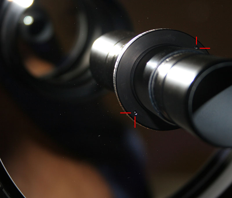
Changing the collimation screws
I hated the crosshead screws that Celestron fit to the secondary mirror for collimation. They require you to point a screwdriver at your secondary in the dark, and as they tighten the driver can tend to 'lift' out of the screw head as you turn it.
So after a friend had successfully changed his collimation screws for a set of hex drive dome head bolts I decided to perform the same modification. I had already ruled out a set of 'Bobs knobs' like those I had fitted to my old C9.25, because these prevent the screw cover plate rotating back over them, and because the secondary of the C14 comes almost flush with the corrector casting and I was worried that the knobs would contact the ground first if the OTA was ever stood on its end.
I used stainless steel M4 dome head screws as sourcing direct replacement imperial stainless dome heads proved to be extremely difficult in the UK. These screws are slightly larger than the originals and require the secondary holder to be drilled out and re-tapped. However they take a larger hex key which gives more of a 'feel' to the collimation adjustment.
This procedure should only be carried out by a person comfortable with the process of drilling and tapping aluminium.
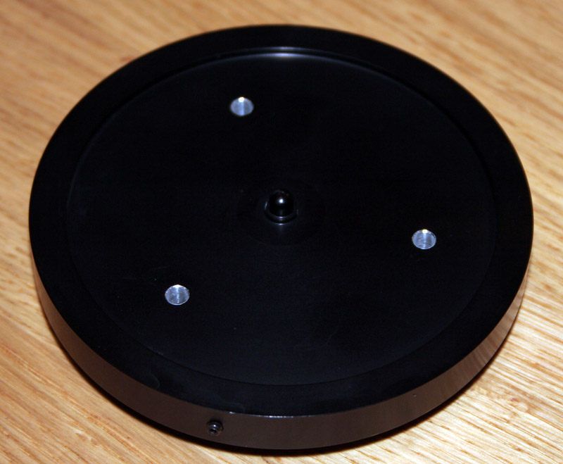
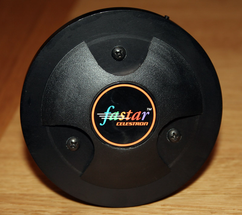 | The front of the secondary Fastar assembly after removal from the OTA. Showing the hated cross head screws. |
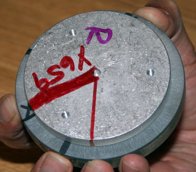
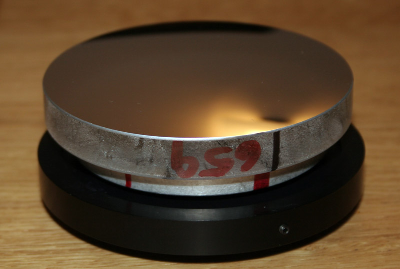 | The rear of the secondary Fastar assembly after removal from the OTA. Make a note of which line is aligned with the locating lug, you will need this for reassembly. |
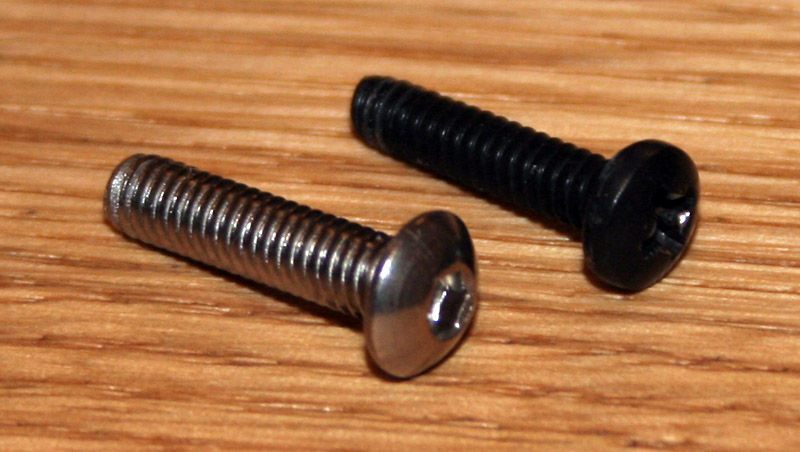 | Next remove one of the original screws and compare it with the replacement to check they are approximately the same size. |
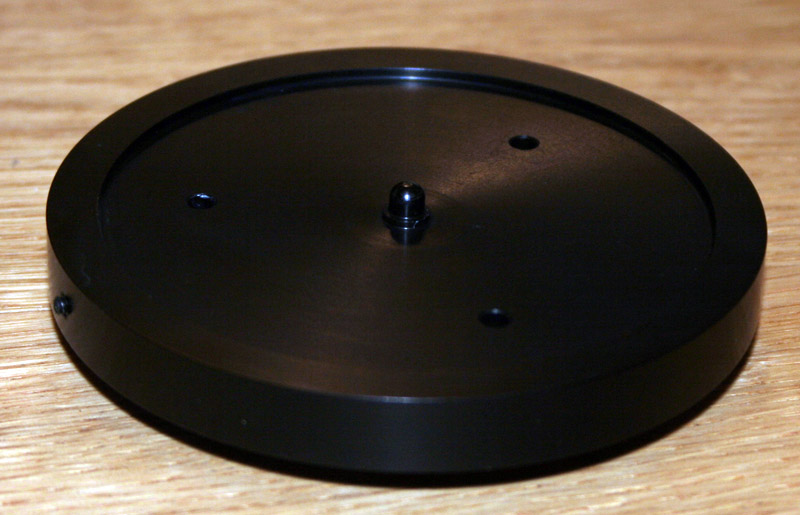 | Remove the rest of the screws and the secondary mirror will detach from the secondary holder front plate (shown here). This image shows the location lug on the side, and the nipple on which the secondary mirror pivots when you adjust collimation. |
 | The three holes in this plate have to be drilled out using a 4mm bit. This photo shows the plate after drilling. |
 | Next the aluminium plate that is attached to the back of the secondary has to be drilled and tapped! Using a 3.3mm bit in a pedestal drill, the plate was offered up to the bit by hand (carefully), this cleans out virtually all of the existing imperial thread and is the correct size for the M4 taps. Care has to be taken to not take the drill bit into the secondary mirror! The first two taps (of a three tap set) were then screwed into the plate to cut the new thread - again be careful that they do not contact the back of the mirror. The final tap was modified by grinding the pointed end off, and adding a very slight bevel to the end. This allows the final tap to cut a thread almost to the bottom of the hole. This photo shows the plate after all three holes had been re-threaded. |
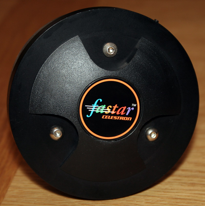 | Reattach the mirror to the front plate - remembering the alignment marks - using the new collimation screws. It should look something like this. |
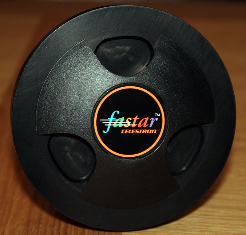 | And just to show that the collimation screw cover still works, here is it closed. Now go and have a well earned drink! |
Bits and bobs required:
- 3x M4 dome head machine screws with 16mm thread length
- 4mm drill bit
- 3.3mm drill bit
- M4 thread tap set
- Grinder and pillar drill
Primary Mirror Problems
I found that my collimation was not holding very well. I'd set it one night and the next time I used the scope it would be off again.
Whilst I had the corrector off for cleaning, I just happened to check the retaining collar on the primary mirror: and found it was unscrewed by at least a turn and a half!
After reading the C14 group it appears that this problem is not unheard of, the collar seems to come loose in transit from Celestron. So it your collimation isn't holding, it may be worth checking out the collar on your scope.
| image to follow | First if you have a late model Fastar OTA, loosen the four corrector centring screws in the corrector casting. Undo each one by exactly half a turn so you can return them to the original positions when refitting the corrector plate. |
| image to follow | Next if you have a Fastar OTA, remove the secondary mirror and put it somewhere very safe - I put mine in a small box. Do not touch the secondary mirror, or place the assembly mirror side down on any surface! Removing the secondary gives you a nice hole in the corrector to hold it by. |
| image to follow | Now unscrew the corrector retaining ring, and remove it. |
| image to follow | Mark the edge of the corrector place and corrector housing in two places at right angle to each other. This will allow you to replace the corrector in the same position. |
| image to follow | Remove the corrector plate and put it somewhere safe. If it is stuck to the gasket, I find inserting the end of wooden clothes peg as shown and applying a gentle leverage pops it off quite easily. |
 | The picture on the left shows the baffle tube, primary mirror and its retaining collar. There are two holes in the collar (indicated in the image), I inserted an Allen key into each hole and used these to snug the collar down. Do not over tighten! Over tightening the collar has been shown to introduce distortions in the primary mirror. However I have found (twice :( ) that unless it is fairly tight it can work loose again (presumably from thermal effects?). It is important that you perform this operation with the OTA vertical. On my first attempt I tightened the collar with the OTA horizontal on a table (so I did not drop anything on the mirror!). When reassembled the primary mirror was obviously not aligned with the mechanical axis. Some weeks later I stripped it down again, loosened the collar, and re-tightened with the OTA vertical, this time the optical and mechanical alignment was much, much better. |
| Replace the corrector plate using the alignment marks you made earlier, and hold in place with the retaining ring and a couple of screws - do not tighten them down yet. | |
| If you have a Fastar OTA, tighten up the corrector centring screws half a turn each to place the corrector in the right position in the casting. Don't worry if this is not central, the offset is to allow for any slight mis-alignment in the primary mirror with the mechanical axis. This doesn't matter for use at f/11, but does when using the OTA at f/1.9 | |
| Now snug down the corrector retaining ring and replace the secondary mirror (if required). |
Internal Fan
In an attempt to combat internal heat plumes on the C14 I have taken a different route from most people. I have seen quite a few C14s that have been modified by having holes cut in the rear casting and had fans fitted to exchange the internal air in order to reach thermal equilibrium.
My approach has been to not try to achieve equilibrium with the environment, but to remove the convection currents that the temperature differential causes. To this end I have taken a two pronged approach:
- I have fitted the OTA with a a thermally insulating dew shield that extends right back to the rear casting. This keeps warmth in the tube, lessening the temperature differential between the mirrors and the internal air.
- I have fitted a small internal fan inside the OTA to break up any convection currents that may form inside the OTA.
My hope is that this will also keep the corrector plate a little warmer for longer and reduce the power requirement on the dew heaters.
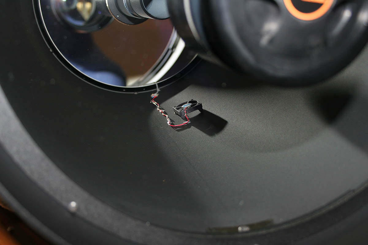 | One view of the internal fan in place, the fan is very small 12V computer job. The power lead is lead out through one of the carriage bolt holes in the rear casting. |
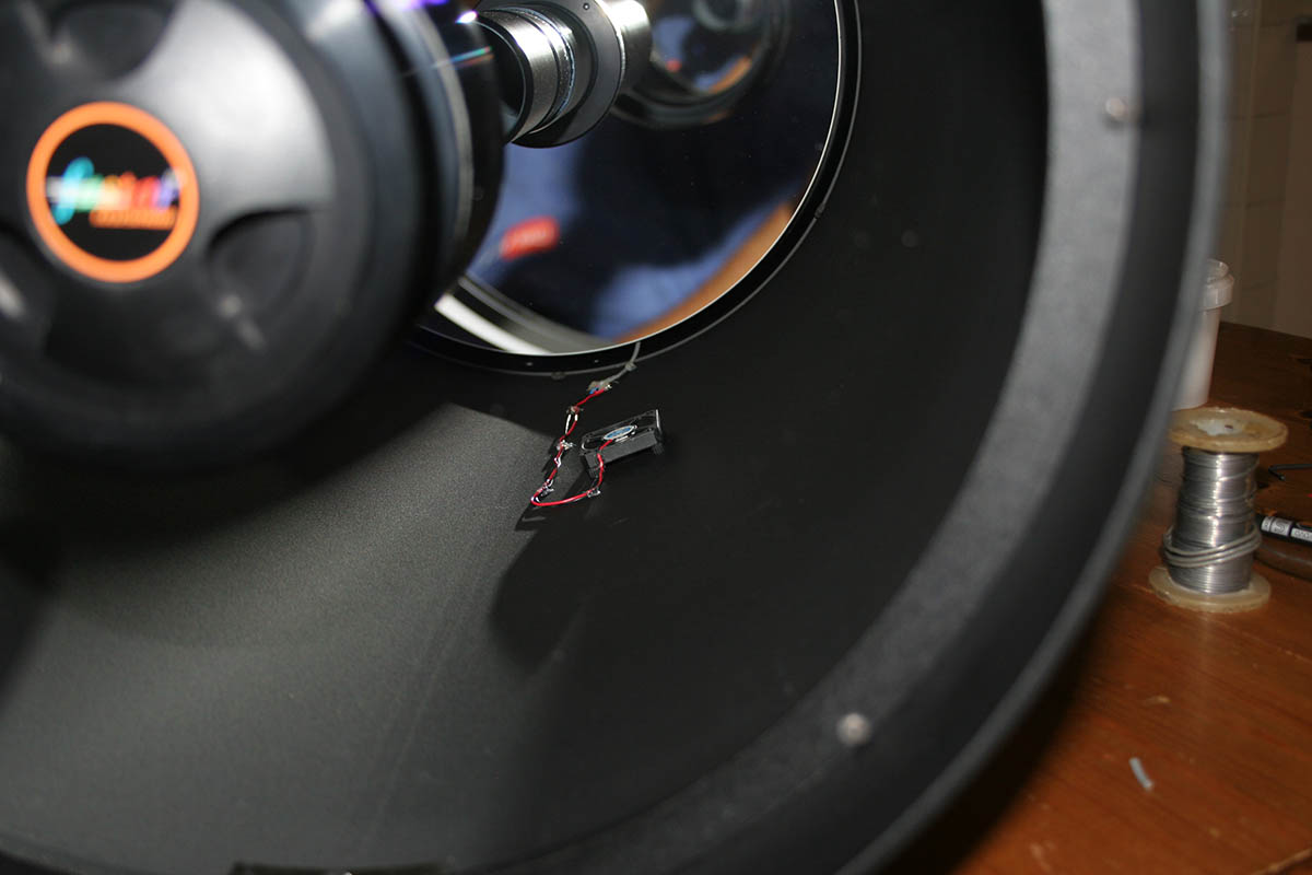 | Everything is held in place with dabs of hot glue to make removal easy if it doesn't work! The fan is held away from the OTA wall with four small rubber pads, again hot glued in place. |
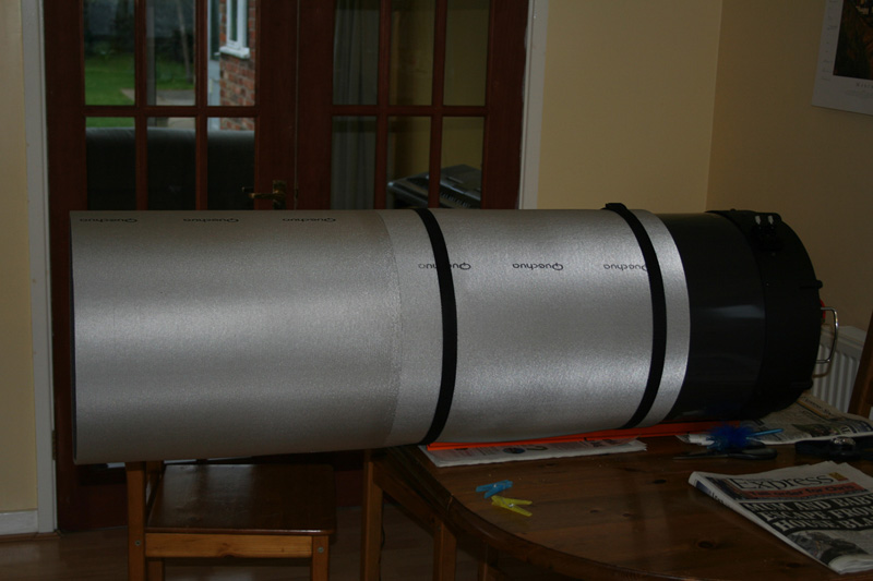 | An early shot of the dew shield, I later modified it so that it now pulls right down to cover the whole of the OTA steel tube. I'll update the picture some time :) Yep, they are camping mats from Decathlon glued together! |
Does it work? Well it is still early days, but the two nights when I did have heat plumes form in the OTA, switching on the fan DID get rid of them and allow much better seeing than before. With keeping the C14 in an observatory it is usually quite well cooled by the time I come to use it. The real test will be this autumn when the temperature differentials between day and night and higher.