Wilmslow Astro
Astronomy from a Cheshire suburb
Losmandy G11 & Gemini
Here are some of the things I've been doing with my G11 and Gemini. I hope you find them of some use.
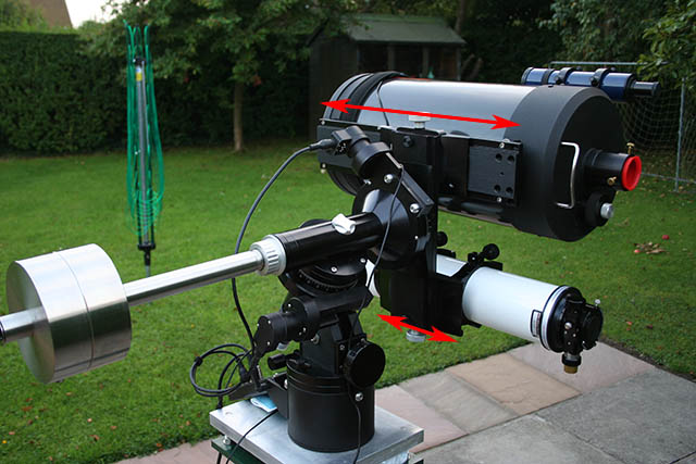
Balancing a side-by-side setup
Gemini/G11 Gearbox information
Replacing the Losmandy Gearbox with a McLennan
My Bearing Block Problem (76 second Periodic Error Issue)
Changing the order of the washer assemblies
I took a look at the default (and recommended elsewhere) order that the washers and spacers are placed on the RA and Declination shafts and decided that they would be better switched around.
I think my assembly order is better because it eliminates a fairly large gap behind the thrust bearing that appears with the standard order. This can only help exclude dust and other contaminates entering the bearing and prolong its life and time between re-lubes.
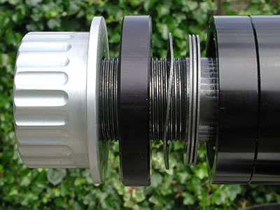 | The 'standard' assembly order, as supplied by Losmandy on my mount. |
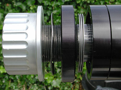 | My re-arranged assembly order. |
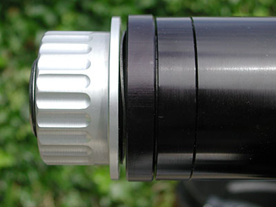 | My order in practice, note the much smaller gap. Though it is hard to see at this resolution, believe me there is still a gap! |
Friction Plate Replacement
If you use your G11 with digital setting circles (or the mark I eyeball), then the Nylon slip clutches fitted to the G11 make sense, you want the clutches to slip smoothly and easily. However if you use the Gemini then you want the clutches quite tight to prevent slippage and loss of alignment. Hmm these criteria seem to be at odds.
The conventional 'fix' is to apply more torque to the clutch knobs, either by replacing them with knobs that have extensions to give you extra grip, or by using something like a strap wrench on the standard knobs.
This seemed like madness to me, stressing the mount in what was a work around for the real problem - which is that the friction plate material is too slippery. So I am on the search for a new material...
I haven't found the ideal candidate yet, but I am now using a real 'high tech' material with some success. Cardboard!
Having replaced the existing Nylon plates with disks cut from a sheet of cardboard of approximately the same thickness, the mount can now be sufficiently 'locked up' with hand pressure alone on the standard clutch knobs to support my C9.25, and Megrez 80 on a side-by-side plate. When slackened slightly it slips quite nicely.
I am concerned about the durability of the cardboard - it may start disintegrating, or 'polish' up and lose its properties - so having proved that the concept works, the search is on for a more durable material with similar friction characteristics. Any suggestions?
back to topPolar Scope Binding Fix
If you have the G11 fitted with Gemini and have the Losmandy polar scope, then you may have noticed that if you adjust the polar scope so that it rotates nicely with the RA clutch loose, then when you tighten the clutch the polar scope starts binding.
The reason for this is that it 'bottoms out' and tightens against the RA shaft its self rather than seating against the RA tensioning knob. The cause of this is that the black spacer provided by Losmandy (see the diagrams above in the washer assembly order section) is slightly narrower than the cage assembly used by the DSC version that it replaces :(
The fix is add an additional thrust washer to bring the RA clutch back along the shaft a little. Some have measured the extra thickness required as 0.125", but it's not critical. Just add an extra washer or two in front of the RA clutch until you stop bottoming out.
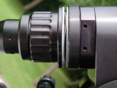
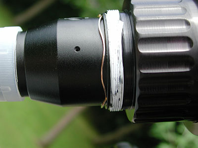
 | The polar scope when fitted to my mount 'as supplied'. I have removed the retaining ring for clarity. Note that the shoulder on the polar scope does not insert fully into the hand knob. The PTFE tape on the threads is there because on my mount, when you tighten the grub-screw on the polar scope retaining ring, it moves slightly and jams the free rotation of the scope. The tape reduces this effect somewhat. |
 | Two extra Nylon washers added (from B&Q plumbing section) to space the hand knob further back. |
 | With the additional washers the polar scope now seats correctly and does not 'wobble' at all. Mine was quite a tight fit at first, I just smoothed things off with some 800 grade wet'n'dry (dry) and it's now perfect. |
Balancing a side-by-side setup
I used to run my scopes side-by-side on the G11 using a Losmandy DSBS plate (alas with the C14 this is no longer possible). I have often seen posts saying how difficult it is to balance such a setup, and if you get it correct for one orientation it will be wrong when you slew the scopes around. I have to say that I have never found it a problem achieving balance, and the second statement is patently false.
When balancing a GEM mount the aim is place the centre of gravity of the scope(s) and weights at the intersection of the RA and Declination axes. If you achieve this then the setup will be balanced in any orientation.
Generally here are only two axes that require balancing for a single scope (or a 'piggyback' setup), if you use a side-by-side arrangement then there are three axes that require balancing. There is one
'gotcha' though, the order that you balance these axies does matter, if you balance in the wrong order then even a single scope may not be correctly balanced at the end.
Below is the procedure I used. It only takes a few minutes.
Step 2 can be omitted for single scopes or piggyback setups, but step 3 (and 2 if applicable) must be completed before step 4 other wise your counter weighting will be wrong.
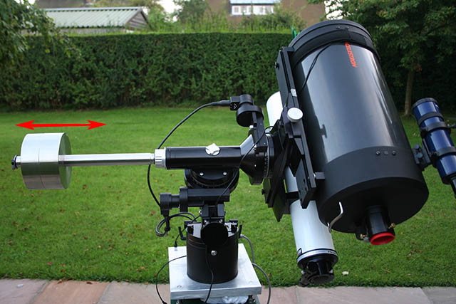 | Step 1. Place the counterweight shaft horizontal and roughly adjust the counterweights to balance your scopes. This balance is not critical at this stage so do not waste too much time getting it perfect. Tighten your R.A. axis clutch so it won't move. |
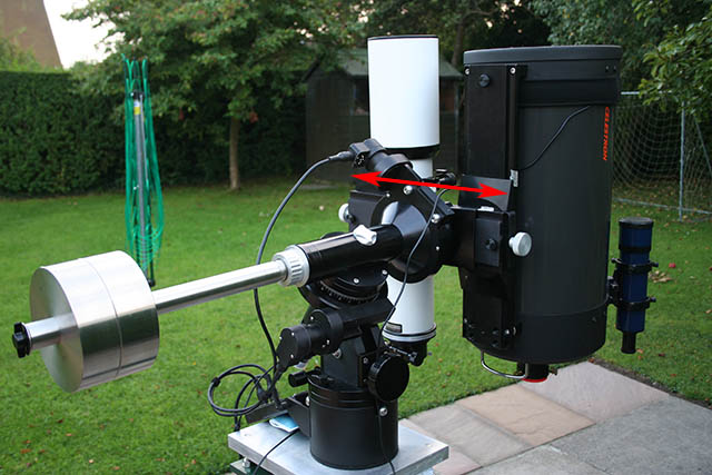 | Step 2. (only applies to side-by-side setups) With the mount in the same position, loosen the Dec. clutch and point the scopes vertically upwards. Now adjust the side by side plate on the mount so that the two scopes balance each other. |
 | Step 3. Now point the scope(s) horizontally, and slide the scope(s) backwards and forwards until they balance (care - tighten the clutch before each adjustment). The centre of gravity is now aligned with the Dec. axis. The scope(s) will now be balanced at every point of rotation of the Dec. axis - try it give them a spin (cables allowing!) Tighten up the Dec. clutch again. |
| Step 4. Now slacken the RA clutch and adjust your counter weights to perfectly balance the scope(s). You have now move the centre of gravity along the Dec. axis until in intersects the R.A. axis - perfect balance. Try it, loosen the clutches and move the mount around, you should find it now balances in every orientation. |
| Notes: If you have any cameras, guiders, dewheaters etc attached to your scopes (I left them off in the pictures for clarity) then the cables should always be routed back the mount. Dangling cables will upset the balance. Don't forget to add your finders/diagonals/eyepieces/dewheaters etc before balancing. After I've balanced my usual setup, I mark the dovetails with a bit of masking tape on the sides so that next I assemble everything I can put it back in almost the right place. Also remember that the G11 works best for imaging with a slight RA weight offset to the East. This keeps the worm driving against a load and you will find it much smoother. Add the weight offset after you have found the correct balance point using the procedure above. |
I hope after reading the procedure you can see why the counterweights must be adjusted after the Dec. axis is balanced. If you adjust your counter weights first, the the centre of gravity probably will not lie on the Dec axis, you are therefore trying the balance against a weight the lies out to the side of the mount. Once you bring the centre of gravity into line with the Dec. axis the amount of counter weight required will change.
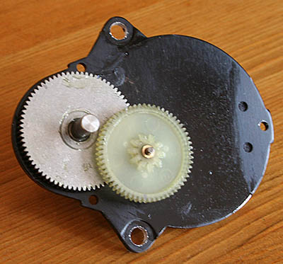
back to topG11/Gemini Gearbox
The Gemini/G11 gearbox/motor assembly has an overall reduction ratio of 25:1. Internal to the gearbox are two gear wheels. The gear attached to the worm has 75 teeth, the intermediate gear has 10 and 60 teeth, the servo motor has 18 teeth.
The reduction ratios are therefore 75:10 and 60:18, or 7.5:1 and 3.333:1
With a worm period of approximately 240 seconds, that means the intermediate gear is turning once every 32 seconds, and the motor once every 9.6 seconds when tracking.
If you have periodic error of around 32 seconds superimposed on the normal 240s period, then your gearbox is probably suspect.
See my page on replacing the standard Losmandy gearboxes with a precision unit from McLennan.
Encoder Resolution
The Losmandy motors are fitted with 256 tick/rev encoders, the main Gemini processor [Gemini has one main processor and two servo controller processors] uses 'whole' ticks for its calculations giving the G11 a native resolution of:
arcsec_per_day/(encoder_ticks * gearbox_ratio * worm_ratio)
1,296,000arcsec/(256ticks*25*360) = 0.5626arcsec/tick
The servo controllers actually use the encoders in quadrature mode (to determine direction of rotation) so they have four times the resolution = 0.140625 arcsec
back to topAdjusting Orthogonality
If you have Gemini, there is a much easier method of adjusting your telescope on the mount than the usual one recommended of pointing the the RA axis at Polaris and swinging the mount round and looking at circles. This method can probably be made to work for other 'goto' systems as well.
This method assumes that you have already accurately polar aligned your mount.
- Select a star either off the bright star list or the full star list that is very close to the meridian (and as close to the celestial equator as possible).
You need to be able to reach this star with the mount flipped to either side. - COLD start your Gemini system - you have to erase any existing pointing model.
- Goto the selected star and Synchronise on it.
- Manually slew the mount to the opposite side.
- Goto the same star again (with Gemini level 4 you can perform a 'Meridian Flip')
- If the scope doesn't point to the star you have to adjust your scope - ignore any error in Declination.
The pointing error you see is twice the error in your orthogonality. - Shim your scope to remove half the error.
- Centre the star again, and Synchronise the Gemini on it.
- Manually slew the mount back to the original side (or 'Meridian Flip' with L4)
- Repeat steps 5-7 until you are satisfied with the result.
Remember if you build a good model in Gemini, the Gemini unit can display what it calculates to be the error in orthogonality.
back to topBearing Block Problem
I had been struggling for some time with a harmonic in my G11's periodic error that was not a integer multiple of the four minute worm period. This has become known as the dreaded 76 second error and is due to the ball bearings in one (or both) of the RA worm bearings rolling past a tight
spot in the bearing race.
I have uploaded an Excel spreadsheet that allows you to calculate how the 76sec error comes about. The spreadsheet is pre-populated with dimensions for a typical G11 worm bearing. Download the spreadsheet here.
I spent ages trying to eliminate this error by:
- replacing the bearings for high precision units
- trying different bearing pre-loads
- twisting the bearing blocks in ever so tiny amounts with a 3/4" spanner (wrench
for those in the USA).
All to no avail, the error could be reduced but was always present to an unacceptable degree. It should be noted that if this none integer harmonic is large it prevents you successfully programming the PEC.
The I thought more about this and realized that the worm blocks only allow you to adjust the bearing alignment in one axis (twisting about the mounting lugs), but it is possible for the blocks to be out in another axis - imagine the blocks 'nodding' up and down along the line of the worm gear. However this adjustment is fixed by the accuracy of the machining of the worm block.
I decided to test my blocks for this error by holding the worm and blocks assembly in compression (to keep everything aligned) and gently lowering it onto the mounting plate on the mount. BINGO! The block furthest from the gearbox did not contact the plate squarely, the inneredge hit first, and pushing the block down onto the plate visibly twisted the bearing block. So when the block was tightened down to its normal position the bearing had a tight spot at the bottom, and was loose at the top.
This may explain why some people have had success by reaming out the bearing housing, possibly it gives the bearing room to twist within the block? That is just speculation.
Anyway, I tried various shims to see what would take up the gap at the rear of the bearing block and found that two or three layers of photocopier paper were about right (the gap isn't big but it is visible).
The next night I downloaded another evaluation copy of PemPro (the first one expired long before I had this solution). The results were fantastic, the 76 second error had all but gone (less that 0.2 arcsecs) and after training the PEC the remaining PE was about the order of the seeing (2 arcsecs). After testing both I ended up deciding that two layers of paper was optimum. I am now one happy bunny :)
If you have problems visualizing the above description the diagram below illustrates the problem with my bearing blocks. Double click the image to see a larger version. Note that though the diagram shows the inner face of the block slanted, I think it may just be the bearing seating that is out of true.

28 June 2008: Stay tuned, a custom made one piece bearing block is in the works, I have high hopes that this will transform the mount. See my preliminary results with a pre-production unit here.
back to topMiscellaneous Specs
Here is a rag-tag of various specifications about the G11 that I have collected over time. This is just to put them together in one place so I don't lose them!
| Polar scope reticule Allen key size = 0.9mm or 0.035 inch |
| Gemini Gearbox Overall reduction ratio = 25:1 Internal ratios = 7.5:1 and 3.333:1 |
| Motor Encoders 256 CPR USDigital Encoders Entire encoder assembly - part# E2-256-079 - http://www.usdigital.com/products/e2/ Just the HED sensor - part# HEDS-9100-F00 |
| Periodic Frequencies Worm = 240s (239.34s) Intermediate gear = 32s Motor = 9.2s |
| Worm bearings (R4ZZ - Shielded) (R4-2RS - Sealed) Internal Diameter = 0.25" 1/4" External Diameter = 0.625" 5/8" Width = 0.196" Timken Super Precision Part numbers: Shielded - SR4CHH, SR4RHH, SR4MCKHH Sealed - SR4CZZ, SR4RZZ, SR4MCKZZ Add 5 or 7 at end of part number for ABEC-5P or ABEC-7P precision http://www.timken.com/industries/superprecision/catalog/catalogs/standard.pdf |
| Approximate bearing quality equivalence ABEC-1 = ISO P0 ABEC-3 = ISO P6 ABEC-5 = ISO P5 ABEC-7 = ISO P4 ABEC-9 = ISO P2 |
| Approximate Instrument bearing quality equivalence ABEC-3P = ISO P6 ABEC-5P = ISO P5A ABEC-7P = ISO P4A ABEC-9P = ISO P2 |
| R.A. & Dec Bearings Axis Needle Roller Bearings: 1.500od X 1.250id X 0.750width (Torrington B-2012) - Original Part 1.500od X 1.250id X 1.000width (Torrington B-2016, SKF BA2016) 1.500od X 1.250id X 1.250width (Torrington B-2020) Clutch Knob Thrust Bearings: 1.937od X 1.250id X 0.0781width Bearing (Torrington NTA-2031) 1.937od X 1.250id X 0.0300width Washer (Torrington TRA-2031) 1.937od X 1.250id X 0.0600width Washer (Torrington TRB-2031) Main Thrust Bearings: 3.750od X 3.000id X 0.0781width Bearing (Torrington NTA-4860) 3.750od X 3.000id X 0.0300width Washer (Torrington TRA-4860 ) 3.750od X 3.000id X 0.0600width Washer (Torrington TRB-4860 ) |
back to top
Gemini A & E Errors
The A & E (azimuth & elevation) errors reported by Gemini when building a model are reported in arc-minutes.
Assuming you are in the counter weight down park position, then...
In the Northern hemisphere:
If you have a A: - (minus) then you have to move the mount counter-clockwise when looking down from above.
If you have a E: - (minus) then you have to lower the counterweight shaft.
In the Southern hemisphere:
If you have a A: - (minus) then you have to move the mount clockwise when looking down from above.
If you have a E: - (minus) then you have to raise the counterweight shaft.
back to topGemini Bootup Codes
The information below was provided by René Görlich on the Gemini Users group:
The characters at boot time indicate the boot progress and conditions detected.
1st dot: internal resources and display initialized
2nd dot: power good, voltage stabilized
3rd dot: SRAM accessible (otherwise "SRAM failure !" will be displayed)
X: the content of the SRAM was reset to default values.
R: RTC was reset ("RTC malfunction" displayed if RTC is not working)
4th dot: RTC initialized
5th dot: SRAM values loaded.
"AG port defect ? " will be displayed if one or more Auto Guider signals are active.
The 'X' is to be expected after a EPROM version change, backup battery change, at low backup battery voltage and so on.
Once an 'X' appears, a "CMOS reset" string is appended to the start-up message, too. Since the initializing is done by the same subroutine as used by the Setup...Reset Defaults menu point, there is no need to take the battery out to renew the SRAM content.
A side effect of pulling the battery out is that the RTC chip will stop working after a while and may then be initialized at the next start-up. In case of problems you may first check and maybe set the UTC date and time and the ALARM time, too.
If the second dot is not displayed and the boot process stops, the circuit board voltage has not stabilized at the nominal 5V voltage and fuse F2 may have to be replaced. Try to remove peripherals in this case (Auto Guider, serial connection, feature port peripherals, axes encoders which may draw too much current) and boot again.
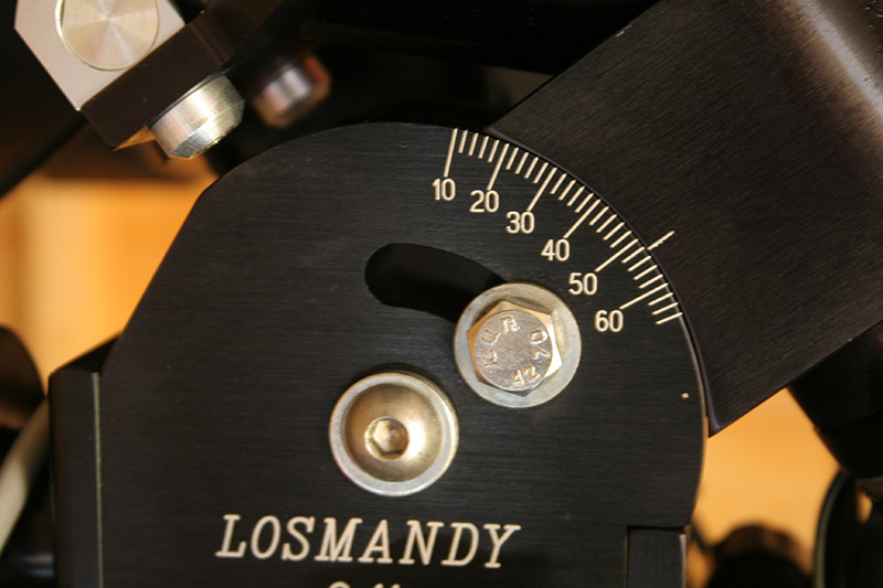
back to topAltitude Clamp Bolts
I have never been very satisfied with the altitude adjustment on the G11, after carefully aligning tightening up the two clamp bolts with an Allen key never seemed to lock the mount solidly. I would apply pressure until the Allen key bent, but the bolt would turn so far then stop. The altitude adjuster knob would still allow me to move the mount if turned reasonably hard.
The solution is simple, replace the cap headed Allen set screws with proper stainless steel 3/8" x 1.25" hexagonal bolts. They do not look as pretty, but a 9/16" ring spanner (wrench) now locks up the mount solidly with only moderate tightening.
 | The original set screws and replacement bolts. Notice how the hex hole in the original screws has distorted under the pressure I was applying! |
 | The new bolts fitted to the G11 mount. They may not look as pretty, but they are far far more functional. Notice just how much larger the purchase area is for wrench! |