Wilmslow Astro
Astronomy from a Cheshire suburb
Aligning the Optics of a C14
This page presents the method I use to align the optics of my C14. The process can be applied to any SCT, and has also been successfully used with a Meade 16" ACF.
Background
The driver for this procedure came when I bought a HyperStar unit for my C14. My corrector plate was noticeably off-centre from new and the HyperStar images showed an asymmetry that required quite a bit of adjustment to correct with the HyperStar collimation screws. At first I re-centred the corrector on the optical axis of the primary mirror using reflections from primary.
This produced nice HyperStar images with the collimation adjusted flat, but the 'normal' SCT images now suffered from a touch of astigmatism. So the quest was on to sort this out for good. My reasoning was that the axis of the primary mirror and the baffle tube had to be aligned first, this is normally done by 'spinning' the primary. Then the secondary mirror has to be centred on the same axis, primarily by adjusting the corrector plate position.
I tried spinning the primary and improved things, but found it very difficult to create a rig sturdy enough to hold the mirror without flexing as I rotated it and watched the reflected laser beam on the roof! However I did improve on the factory alignment and this did bring the HyperStar and SCT modes ideal placements 'closer' to each other.
My Method
Warning: This procedure carries the risk of damaging your OTA, it will certainly invalidate any warranty, and should only be carried out by a competent person. Do not blame me if you try this and it all goes horribly wrong. Only contemplate doing this if you optics are really out whack and you have to do something to sort them out.
This is the method I have used successfully on my C14 and a Meade 16" ACF, it may not be the best way of doing it, but it is relatively simple to perform and does not require any fancy test tools.
You will need:
- A laser collimator - 2" is best, check it is collimated before you start!
- A piece of card about 200mm square
- A small torch or bright LED
- Preferably a 'tool' to fit the primary mirror retaining collar
- Compasses for drawing circles
- Ideally some sort of adjustable stand to hold the card upright
Before you start you have to be comfortable taking your C14 apart, and be aware of how the components (corrector, secondary mirror, secondary holder) are aligned and how the index marks work in relation to each other - if there aren't any, you ARE going to make index marks as you take every thing apart aren't you?! If you are not comfortable with this level of strip down, STOP NOW, this procedure is probably not for you.
| The primary reference for whole OTA is the baffle tube. The baffle tube is to all intents fixed and non-adjustable, and so defines the primary axis to which everything else has to be aligned. | |
 | The first thing to check is the OTA is mechanically aligned with the baffle tube. In order to do this I spun the OTA on the baffle and checked for run out of the machined recess in the front corrector cell where the corrector plate sits. Guess what? Mine was out by about 2mm, which explains why it came from the factory with the corrector pushed hard up against the cell on one side, and why I got to the same position on previous optics alignment attempts. |
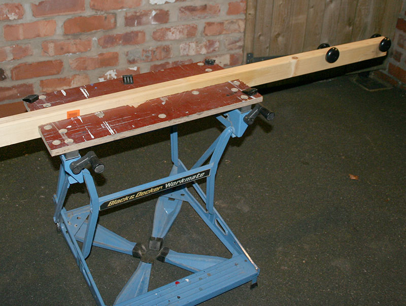
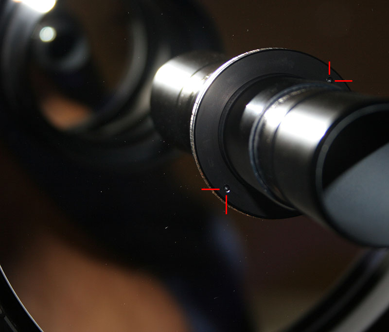
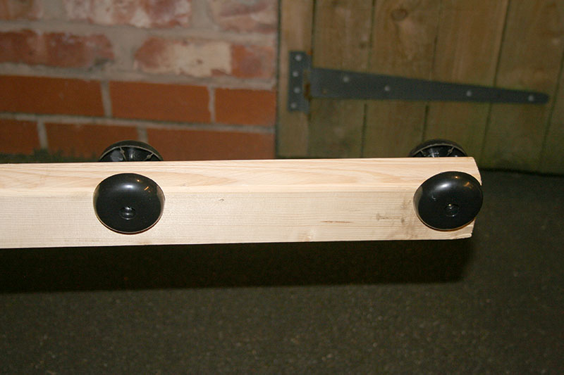 | To spin the OTA I created the rig shown in the photographs left and above. Remove the corrector and primary mirror from the OTA. A pointer attached or held to the workbench is used to see any run out. You can visually see errors to a fraction of a millimetre, you do not need any fancy dial gauges. |
 | If you do have any run out (mine was about 2mm), then loosen the nuts/screws that hold the rear casting to the OTA and use a piece of wood and mallet to gently tap the tube in the direction required. You will probably find the tube is seated hard back against the rear casting, so the initial adjustments are going to be tapping the front casting forwards away from the rear casting. Once the OTA tube is mechanically set you are ready to align the optics... |
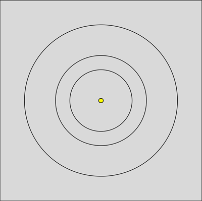 | Draw a set of bulls eye rings centred on the card. A selection of sizes, say four different rings - it's not really critical.br /> Punch a pin hole in the centre of the card, not too small as you want a reasonable amount of light to through. I stuck some foil on the back of the card to make it really opaque to light around the pin hole. |
| Remove the corrector plate from the OTA, and place the laser directly into a 2" visual back. Avoid using a focuser on the back of the OTA if at all possible, I placed the laser into an Astro Physics 2" adapter. Double check that your laser is aligned properly, and try rotating it in the rear of the OTA to make sure the spot doesn't move. Getting the laser square in the baffle tube is critical. | |
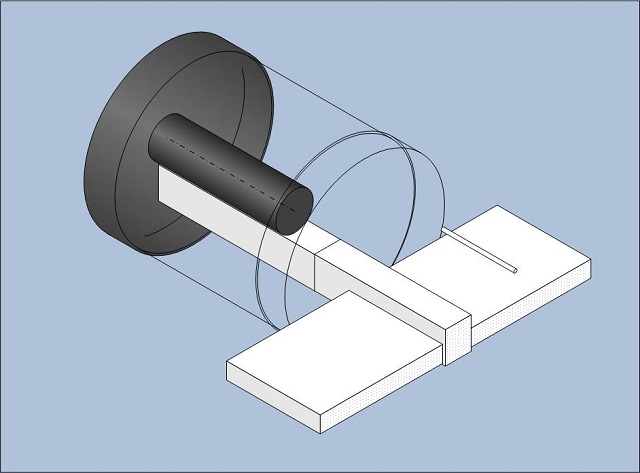
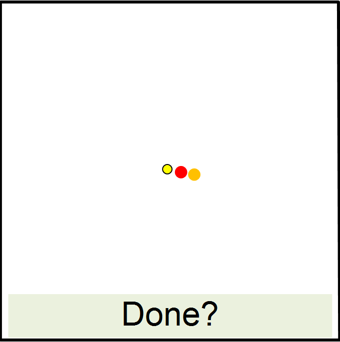
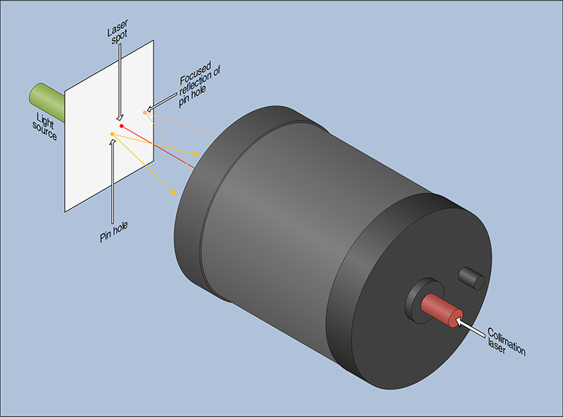 | This diagram shows the general layout. The idea is that: - The laser will define the central optical axis of the baffle tube - Light shines through the pin hole in the card, is reflected back from the spherical primary and focused back on the card. - When the primary mirror is aligned the pin hole, the reflected image of the pin hole and the laser spot will all coincide. The card will have to be placed at the centre of curvature of the primary, this is 60" from the primary or about 3 feet in front of the OTA. |
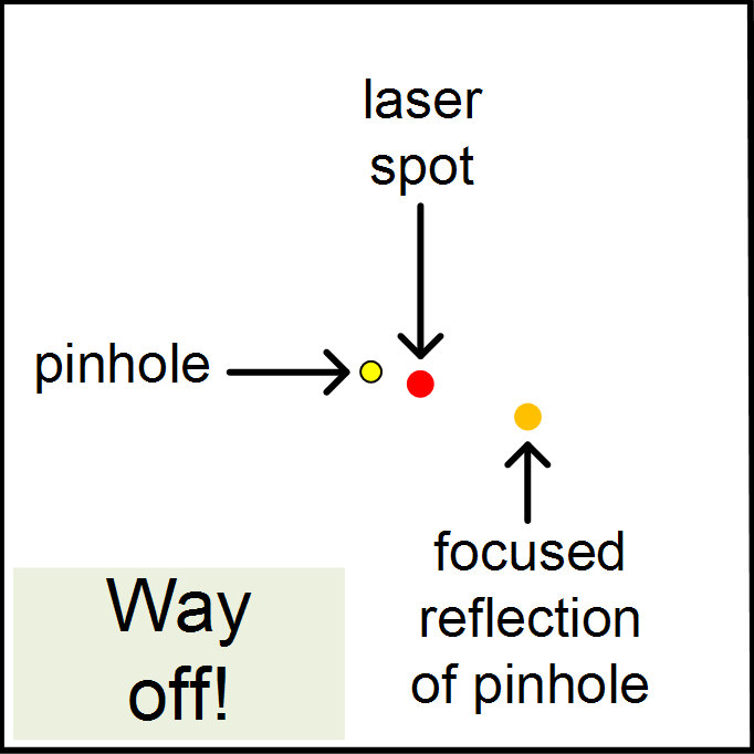 | You will probably find that the spots are not evenly spaced, like the diagram on the left. Determine which direction the pin hole and its reflection are offset from the laser spot. With a gloved finger you can press on the edge of the primary mirror to see which section has to be pressed down in order to centralise the laser spot between the other two spots. Make a note of this orientation. |
| This method of aligning the primary does not require the removal of the primary from the mirror support casting, it relies on the fact that there is some give in material that Celestron (RTV) and Meade (What looks like masking tape) use between the mirror and the baffle tube. By varying the point at which maximum pressure is applied, a very slight tilt can be induced in the mirror. | |
 | Now you need to remove the primary mirror retaining collar (see my other C14 page). Then remove the cork gasket that usually sticks to the primary. Using the gasket as a template I cut an arc of sticky backed flocking about a third of the circumference long and stuck it to the cork. Replace the gasket and collar and tighten up. |
 | Go back a step and recheck the alignment, hopefully it will be a bit better. If you have gone the wrong way, spin the gasket 180 degrees. Not far enough? add another piece of flocking on top of the previous piece, this time a bit smaller, about a quarter of the circumference. Repeat the check... You get the idea. |
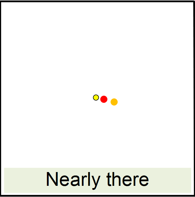
 | Eventually (hopefully without too many iterations) you will get something like this, where the spots are evenly spaced. You can also... |
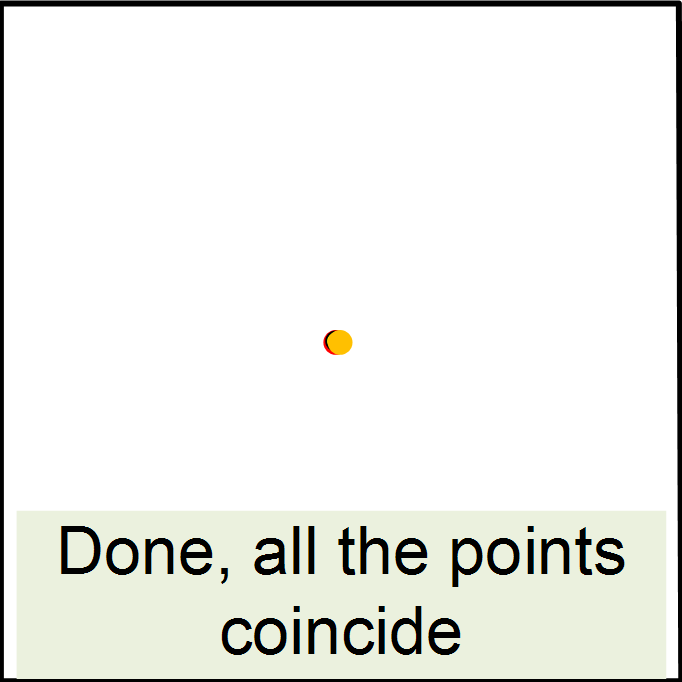 | ...bring all the spots together over the pin hole, and they should merge. Congratulations you now have the primary mirror aligned with the axis of the baffle tube. |
Now you need to centre the secondary mirror on the same axis. Before you do this there are some checks you should perform.
Happy with all this, then continue... | |
 | Replace the corrector plate, and set up your test rig again. This time however move the card past the point at which the pinhole reaches focus. Put the laser spot over the central pin hole. You will now see an larger disk with a shadow of the secondary holder on it. If the secondary needs adjusting the shadow will be offset like the diagram here. |
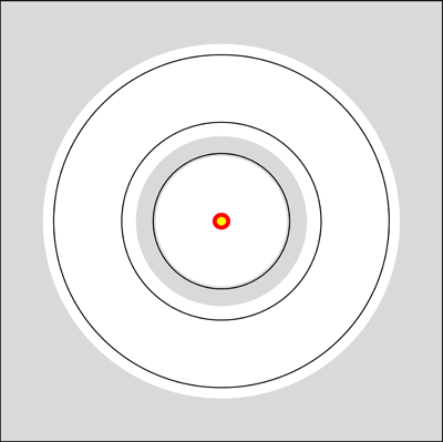 | Now adjust the corrector plate to centralise the shadow. This is where the circles you drew on the card come into their own. You can move the card back and forth so that the size of the secondary shadow matches one of the rings. This makes it fairly easy to determine even small amounts of offset. |
| Alternative method: Now the OTA is mechanically aligned, you can centre the secondary holder by simply adding a pinhole peep at the rear of the OTA. If this is almost flush with back of the baffle tube, it is possible to see the edge of the secondary holder inside the far end of the baffle tube. If the peep hole is sited any further back it is impossible to see the secondary holder. This is good check to perform anyway to confirm that every is as close to perfect as you can get. | |
| OK, you're almost done. Replace the secondary mirror and collimate it as normal. You should now have nice doughnuts and no astigmatism in SCT mode, and your Hyperstar may not even need the slightest tweak of collimation to get a flat field. |
Some other checks that you may want to perform:
- Is your focuser square to the baffle tube? A friend replaced his MoonLite focuser on the back of his SCT after the above procedure and popped the laser in, whoa, no where near square! A bit of shimming between the focuser and its mounting ring and the focuser was then square to optical axis. The culprit seemed to be the adapter ring which did not tighten down square on the rear port of the SCT.